After talking about PMOS, let's take a look at the reverse protection circuit of NMOS this time.
For simple gate drive circuit designs, we use NMOS for reverse protection because of its lower cost.
PMOS is generally placed on the high side of the circuit, while NMOS is placed on the low side. Their functions are similar. However, the reverse protection structure of NMOS, with its power ground and load ground separated, is rarely used in automotive electronic product designs.
This is because low-side switching has certain limitations and potential problems with poor grounding, so it is still recommended to use high-side switching for power.
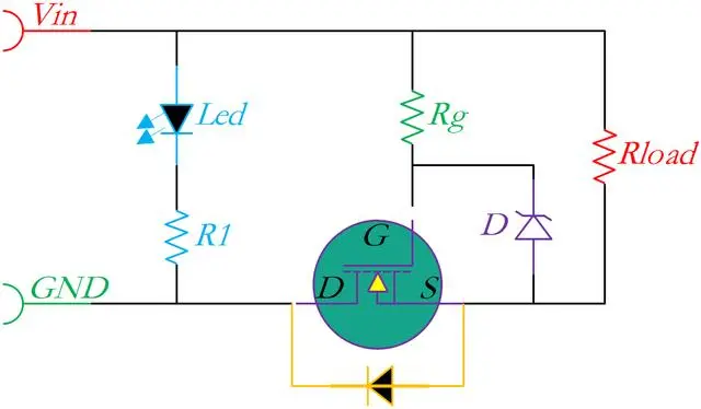
Traditional NMOS reverse protection
What if we add a drive IC?
When designing a reverse protection circuit using NMOS and a voltage regulator IC, the NMOS needs to be placed on the high side, and the drive IC also draws power from the high side.
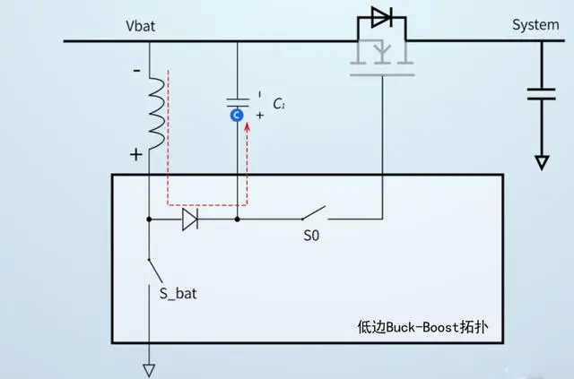
Optimized NMOS and drive IC circuit
This will generate an internal voltage greater than the input voltage (VIN) to provide power for the NMOS's gate (VGS).
Using a drive IC can adopt a buck-boost scheme.
There are two advantages to using a buck-boost topology: one is to provide greater driving current capability.
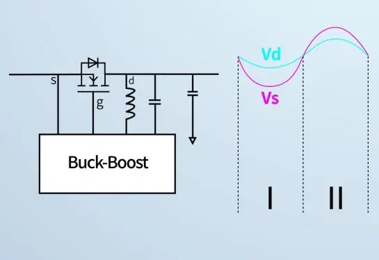
When the input voltage is superimposed at 100kHz with a peak value of 2V, the input voltage is consistent with the source voltage, and the system voltage is consistent with the drain voltage.
When the source voltage is lower than the drain voltage, the input voltage (VIN) will be lower than the system voltage, the MOSFET is driven to turn off, and the body diode provides reverse protection, preventing the flow of capacitor current.
If the source voltage exceeds the drain voltage, the input voltage exceeds the system voltage, the MOSFET is driven to conduct, which can avoid the conduction of the body diode and affect the circuit efficiency.
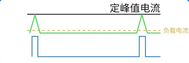
The second advantage is to improve EMC performance.
By adopting fixed peak current control, smaller loads can correspond to lower fSW, and the lighter the load, the lower the switching frequency. Moreover, the MOSFET is a voltage-controlled device with small current consumption and low switching frequency, almost no EMI problem.
In addition to the above two advantages of providing greater driving current capability and improving EMC performance, it also has the advantages of lower gate voltage drop, lower loss, and temperature rise.
Therefore, in some simple drive circuit designs, using NMOS for reverse protection can be more cost-effective.
* 如果您需要申请我司样品,请填写表格提交,我们会24小时内回复您